![]()

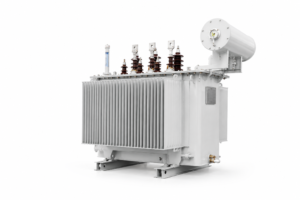
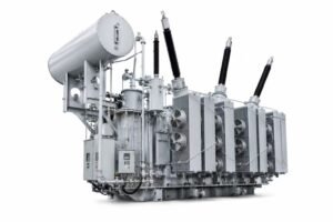
Oil Immersed Transformer
Excellent economic performance:
No-load current reduces by an average of 60%~80%,
No-load loss cuts down by an average of 25%~35%.
Long service life:
Thetransformer tank adopts fully sealed structure; the tank and tank flange can be connected by bolts or welding. Transformer oil is isolated from air to extend service life.
High operational reliability:
Components related to tank sealing are optimized to improve reliability, and advanced manufacturing processes are applied to guarantee stable sealing performance.
Small floor space:
Corrugated sheet radiator is adopted for transformer tank. Thermal expansion and contraction of corrugated plates with oil temperature variation replaces the function of conservator. The corrugated tank features elegant appearance and small floor occupation.
S11(M)-630~31500/35 Low-lors And Non-exciting Regulation Transformer
| Rated capacity (kVA) |
Rated voltage and tapping range | Vector group | No load Losses (W) |
On load Losses (W) |
Short-circuit Impedance % |
No load Current % |
||
|---|---|---|---|---|---|---|---|---|
| HV | tapping range | LV | ||||||
| 630 | 35 | ±5% | 3.15 6.3 10.5 |
Yd11 | 830 | 7870 | 6.5 | 1.10 |
| 800 | 980 | 9410 | 1.00 | |||||
| 1000 | 1150 | 11540 | 1.00 | |||||
| 1250 | 1410 | 13940 | 0.90 | |||||
| 1600 | 1700 | 16670 | 0.80 | |||||
| 2000 | 2180 | 18380 | 0.70 | |||||
| 2500 | 2560 | 19670 | 0.60 | |||||
| 3150 | 35-38.5 | ±5% | 3.15 6.3 10.5 |
Yd11 | 3040 | 23090 | 7.0 | 0.56 |
| 4000 | 3620 | 27360 | 0.56 | |||||
| 5000 | 4320 | 31380 | 0.48 | |||||
| 6300 | 5250 | 35060 | 0.48 | |||||
| 8000 | 3.15 3.3 6.3 |
Ynd11 | 7200 | 38480 | 7.5 | 0.42 | ||
| 10000 | 8700 | 45320 | 0.42 | |||||
| 12500 | 10080 | 53870 | 0.40 | |||||
| 16000 | 35-38.5 | ±2×2.5% | 6.6 10.5 11 |
Ynd11 | 12160 | 65840 | 8.0 | 0.40 |
| 20000 | 14400 | 79520 | 0.40 | |||||
| 25000 | 17020 | 94050 | 0.32 | |||||
| 31500 | 20220 | 112860 | 0.32 | |||||
S11(M)-30~1600/10 Low-loss And Non-exciting Regulation Transformer
| Rated capacity (kVA) |
Rated voltage and tapping range | Vector group | No load Losses | On load Losses | Short-circuit Impedance % |
No load Current % |
||
|---|---|---|---|---|---|---|---|---|
| HV | tapping range | LV | (W) | (W) | ||||
| 30 | 6 6.3 10 10.5 11 |
±5% ±2×2.5% |
0.4 | Dyn11 Yyn0 |
100 | 630/600 | 4.0 | 0.80 |
| 50 | 130 | 910/870 | 0.75 | |||||
| 63 | 150 | 1090/1040 | 0.75 | |||||
| 80 | 180 | 1310/1250 | 0.70 | |||||
| 100 | 200 | 1580/1500 | 0.65 | |||||
| 125 | 240 | 1890/1800 | 0.65 | |||||
| 160 | 280 | 2310/2200 | 0.60 | |||||
| 200 | 340 | 2730/2600 | 0.50 | |||||
| 250 | 400 | 3200/3050 | 0.50 | |||||
| 315 | 480 | 3830/3650 | 0.45 | |||||
| 400 | 570 | 4520/4300 | 0.45 | |||||
| 500 | 680 | 5410/5150 | 0.40 | |||||
| 630 | 810 | 6200 | 4.5 | 0.40 | ||||
| 800 | 980 | 7500 | 0.35 | |||||
| 1000 | 1150 | 10300 | 0.35 | |||||
| 1250 | 1360 | 12000 | 0.30 | |||||
| 1600 | 6 6.3 10 10.5 11 |
±5% ±2×2.5% |
0.4 | Dyn11 Yyn0 |
1640 | 14500 | 4.5 | 0.30 |
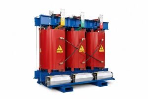
Amorphous Alloy Transformer
| Model | Voltage combination | Connection symbol | No-load loss | Load(w) 100℃ | No load Current % |
||
|---|---|---|---|---|---|---|---|
| HV | HV tap range | LV(kV) | (W) | (B) | |||
| SBH15-30 | 6 6.3 10 |
±5% or ±2×2.5% |
0.4 | Dyn11 | 33 | 630 | 1.5 |
| SBH15-50 | 43 | 910 | 1.2 | ||||
| SBH15-63 | 50 | 1090 | 1.1 | ||||
| SBH15-80 | 60 | 1310 | 1 | ||||
| SBH15-100 | 75 | 1580 | 0.9 | ||||
| SBH15-125 | 85 | 1890 | 0.8 | ||||
| SBH15-160 | 100 | 2310 | 0.6 | ||||
| SBH15-200 | 120 | 2730 | 0.6 | ||||
| SBH15-250 | 140 | 3200 | 0.6 | ||||
| SBH15-315 | 170 | 3830 | 0.5 | ||||
| SBH15-400 | 200 | 4520 | 0.5 | ||||
| SBH15-500 | 240 | 5410 | 0.5 | ||||
| SBH15-630 | 320 | 6200 | 0.3 | ||||
| SBH15-800 | 380 | 7500 | 0.3 | ||||
| SBH15-1000 | 450 | 10300 | 0.3 | ||||
| SBH15-1250 | 530 | 12000 | 0.2 | ||||
| SBH15-1600 | 6 6.3 10 |
±5% or ±2×2.5% |
0.4 | Dyn11 | 630 | 14500 | 0.2 |